Inter-VLAN routing is a network configuration technique that allows communication between devices on different VLANs (Virtual Local Area Networks) within the same network
VLANs are commonly used to segment a network, improving performance and security by isolating traffic within each VLAN. However, this segmentation also creates a communication barrier, as devices in separate VLANs cannot communicate by default. Inter-VLAN routing overcomes this limitation by enabling traffic to pass between VLANs.
Configuring inter-VLAN routing typically involves setting up VLAN interfaces, assigning IP addresses to each VLAN, and enabling routing on the network device. This setup is essential in larger or segmented networks where different departments or user groups need to communicate securely and efficiently, enhancing network flexibility and management while maintaining the security benefits of VLAN segmentation.
There are three main methods for configuring inter-VLAN routing:
- Traditional,
- Router-on-a-Stick, and
- Multi-Layer Switch
The traditional method, which is also known as “Legacy” Inter-VLAN Routing, is necessary where the switches in use do not have routing capabilities. In the Router-on-a-Stick method, a single physical router interface is configured with multiple subinterfaces, each associated with a unique VLAN. This allows the router to route traffic between VLANs. In contrast, the Multi-Layer Switch method relies on Layer 3 switches, which are switches with routing capabilities. These can perform inter-VLAN routing directly at the switch level.
Effectively, the Multi-Layer Switch method is the same as the Traditional method but uses better equipment. Routing at the switch, where possible, improves performance and reduces the need for external routing hardware.
In this guide, we will walk you through all three methods.
Traditional Inter-VLAN Routing
This method of inter-VLAN routing relies on a router with multiple physical interfaces. Each interface is usually connected to the switch, one for each VLAN. The switch ports connected to the router are placed in access mode. Each router interface can then accept traffic from the VLAN associated with the switch interface that it is connected to, and traffic can be routed to the other VLANs connected to the other interfaces. This means that each of the routers’ interface IP addresses would then become the default gateway address for each host in each VLAN.
Let’s take a look at the diagram shown in Figure 1.0 below. If Host A on VLAN 10, wants to send a message to Host B on VLAN 20, it would take the following steps:
- Host A checks whether the destination IP address is in its VLAN; if it is not, the traffic will be forwarded to its default gateway on interface Fa0/0 on the router.
- Host A then sends an ARP request to the switch to determine the MAC address of the Fa0/0 interface on the router. Once the router replies, Host A sends the frame to the router as a unicast message, where it is then directly forwarded out the trunk interface to the router.
- When the router receives the frame, it determines the destination IP address and interface from the routing table.
- The router then sends an ARP request out the interface connected to the destination VLAN (VLAN 20), which corresponds to interface Fa0/1 on the router.
- When the switch receives the message, it floods it to its ports, which then triggers Host B to reply with its MAC address.
- The router then uses the information gathered to forward the message finally to Host B on VLAN 20 as a unicast frame through the switch.

To configure traditional inter-VLAN routing on a Cisco device, in accordance with the diagram shown in Figure 1.0 above, use the IP addresses shown in Table 1.0 and follow the steps below:
Device | Interface | VLAN ID | IP Address | Subnet Mask | Default Gateway |
|---|---|---|---|---|---|
Router | Fa0/0 | VLAN 10 | 192.168.10.1 | 255.255.255.0 | N/A |
Fa0/1 | VLAN 20 | 192.168.20.1 | 255.255.255.0 | N/A |
|
Host A | NIC | VLAN 10 | 192.168.10.10 | 255.255.255.0 | 192.168.10.1 |
Host B | NIC | VLAN 20 | 192.168.20.20 | 255.255.255.0 | 192.168.20.1 |
Table 1.0 IP address details for Figure 1.0
Step 1: Create VLANs (VLANs 10 and 20) on the switch
Description | Command |
|---|---|
Enter global configuration mode | Switch# conf t |
Create VLAN 10 | Switch(config)# vlan 10 |
Give a name to VLAN 10 | Switch(config-vlan)# name Admin-dept |
Create VLAN 20 | Switch(config-vlan)# vlan 20 |
Give a name to VLAN 20 | Switch(config-vlan)# name Finance-dept |
Exit the VLAN config. mode | Switch(config-vlan)# exit |
Check if the VLANs were created | Switch # show vlan brief |
Step 2: Assign the VLANs to switch port
Description | Command |
|---|---|
Enter global configuration mode | Switch# conf t |
Enter interface config. mode for fa0/2 | Switch(config)# interface fa0/2 |
Set the port to access mode | Switch(config-if)#switchport mode access |
Assign VLAN 10 to interface fa0/2 | Switch(config-if)#switchport access vlan 10 |
Exit the interface | Switch(config-if)# exit |
Enter interface configuration for fa0/3 | Switch(config)# interface fa0/3 |
Set the port to access mode | Switch(config-if)#switchport mode access |
Assign VLAN 20 to interface fa0/3 | Switch(config-if)#switchport access vlan 20 |
Exit the interface | Switch(config-if)# exit |
Now at this stage, when you try to ping between Host A and Host B, the ping fails because the two PCs are on separate networks. The router is not yet configured for inter-VLAN routing, so they can not communicate with one another. Our next step is to configure inter-VLAN routing to enable communication between the VLANs.
Step 3: Configure the IP addresses on the router
Description | Command |
|---|---|
Enter global configuration mode | Router# conf t |
Enter interface config. mode for fa0/0 | Router(config)# interface fa0/0 |
Configure IP address and subnet mask | Router(config-if)#ip address 192.168.10.1 255.255.255.0 |
Activate the interface | Router(config-if)#no shutdown |
Exit the interface | Router(config-if)#exit |
Enter interface config. mode for fa0/1 | Router(config)# interface fa0/1 |
Configure IP address and subnet mask | Router(config-if)# ip address 192.168.20.1 255.255.255.0 |
Activate the interface | Router(config-if)#no shutdown |
Exit the interface | Router(config-if)# exit |
Save configuration | Router# copy running-config startup-config |
Now at this juncture, if you try to ping between Host A and Host B, it will be successful because the two VLANs are now interconnected through the router.
Traditional inter-VLAN routing happens to be the earliest form of inter-VLAN routing. However, this method of inter-VLAN routing is not efficient. It is archaic, and no longer employed in today’s switched networks. This is because routers have a limited number of physical interfaces that can be used to connect to different VLANs. Therefore, as the number of VLANs increases on a network, the approach of having one router physical interface per VLAN becomes unsustainable due to the inherent hardware limitations of a router. In order to overcome some of the issues associated with traditional inter-VLAN routing, a new method known as router-on-a-stick was invented.
Router-on-a-Stick Inter-VLAN Routing
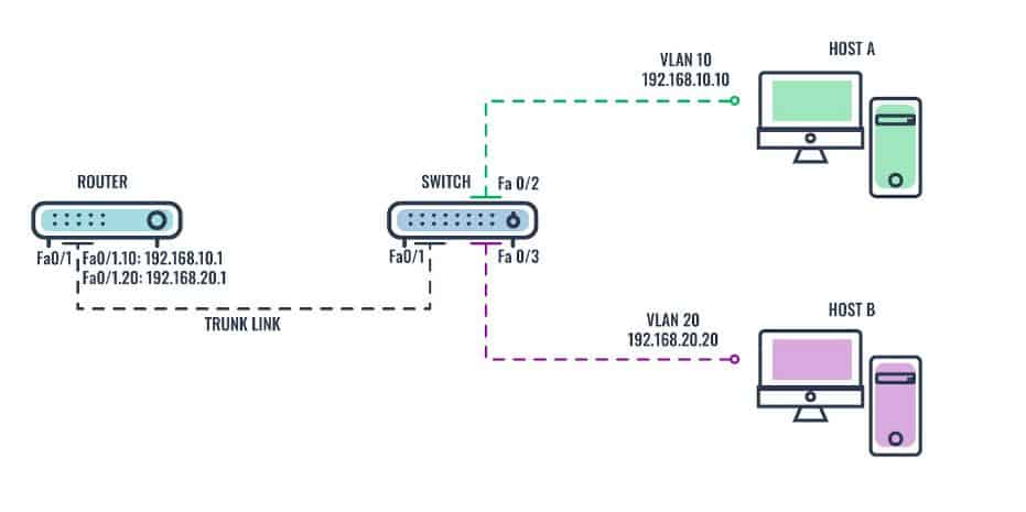
A router-on-a-stick is a method of inter-VLAN routing in which the router is connected to the switch using a single physical interface, hence the name router-on-a-stick. Most modern inter-VLAN routing implementations are designed using this method. Unlike the traditional inter-VLAN routing method, router-on-stick does not require multiple physical interfaces on both the router and the switch. Instead, the router’s operating system makes it possible to configure the router interface to operate as a trunk link, which is then connected to a switch port that is configured in trunk mode. This implies that only one physical interface is required on the router and the switch to route packets between multiple VLANs. IEEE 802.1Q (Dot1q) protocol—which defines a system of VLAN tagging for Ethernet frames, is used to provide multi-vendor VLAN support. Prior to the introduction of the 802.1Q standard, several proprietary protocols such as Cisco Inter-Switch Link (ISL) [PDF link] and 3Com’s Virtual LAN Trunk (VLT), were used.
The single physical interface on the router is linked to logical (virtual) subinterfaces, which can be configured with multiple IP addresses that correspond to the VLANs on the switch. Each subinterface is configured for different subnets corresponding to their VLAN assignment to facilitate logical routing. The router performs inter-VLAN routing by accepting traffic from all the VLANs. It then determines the destination network based on the source and destination IP in the packets. After a routing decision is made based on the destination VLAN, it then forwards the data frames to the switch with the correct VLAN information through the same physical interface used to receive the traffic.
Let’s take a look at the diagram shown in Figure 2.0 below. If Host A on VLAN 10, wants to send a message to Host B on VLAN 20, the steps it would take are as follows:
- Host A sends its unicast traffic to the switch.
- The switch then tags the unicast traffic as originating on VLAN 10 and forwards it out its trunk link to the router.
- The router accepts the tagged unicast traffic on VLAN 10 and routes it to VLAN 20 using its configured subinterfaces.
- The unicast traffic is tagged with VLAN 20 as it is sent out the router interface to the switch.
- The switch removes the VLAN tag of the unicast frame and forwards the frame directly to Host B on port Fa0/3.

To configure router-on-a-stick inter-VLAN routing on a Cisco device, in accordance with the diagram shown in Figure 2.0 above, use the IP addresses shown in Table 2.0 and follow the steps below:
Device | Interface | VLAN ID | IP Address | Subnet Mask | Default Gateway |
|---|---|---|---|---|---|
Router | Fa0/1.10 | VLAN 10 | 192.168.10.1 | 255.255.255.0 | N/A |
Fa0/1.20 | VLAN 20 | 192.168.20.1 | 255.255.255.0 | N/A |
|
Host A | NIC | VLAN 10 | 192.168.10.10 | 255.255.255.0 | 192.168.10.1 |
Host B | NIC | VLAN 20 | 192.168.20.20 | 255.255.255.0 | 192.168.20.1 |
Table 2.0 IP address details for Figure 2.0
Step 1: Create VLANs (VLANs 10 and 20) on the switch
Description | Command |
|---|---|
Enter global configuration mode | Switch# conf t |
Create VLAN 10 | Switch(config)# vlan 10 |
Give a name to VLAN 10 | Switch(config-vlan)# name Admin-dept |
Create VLAN 20 | Switch(config-vlan)# vlan 20 |
Give a name to VLAN 20 | Switch(config-vlan)# name Finance-dept |
Exit the VLAN config. mode | Switch(config-vlan)# exit |
Check if the VLANs were created | Switch # show vlan brief |
Step 2: Assign the VLANs to switch ports
Description | Command |
|---|---|
Enter global configuration mode | Switch#conf t |
Enter interface configuration mode for fa0/2 | Switch(config)# interface fa0/2 |
Set the port to access mode | Switch(config-if)#switchport mode access |
Assign VLAN 10 to interface fa0/2 | Switch(config-if)#switchport access vlan 10 |
Exit the interface | Switch(config-if)# exit |
Enter interface configuration for fa0/3 | Switch(config)# interface fa0/3 |
Set the port to access mode | Switch(config-if)#switchport mode access |
Assign VLAN 20 to interface fa0/3 | Switch(config-if)#switchport access vlan 20 |
Exit the interface | Switch(config-if)# exit |
Enter interface configuration for fa0/1 | Switch(config)# interface fa0/1 |
Set the port to trunk mode | Switch(config-if)#switchport mode trunk |
Exit the interface | Switch(config-if)# exit |
Save configuration | Switch# copy running-config startup-config |
Step 3: Configure the IP addresses on the router
Description | Command |
|---|---|
Enter global configuration mode | Router# conf t |
Enter sub-interface config. mode for fa0/1.10 | Router(config)# interface fa0/1.10 |
Set encapsulation type to 802.1Q and assign VLAN 10 to the virtual interface | Router(config-subif)# encapsulation dot1Q 10 |
Configure IP address and subnet mask | Router(config-subif)#ip address 192.168.10.1 255.255.255.0 |
Exit the sub-interface | Router(config-subif)#exit |
Enter sub-interface config. mode for fa0/1.20 | Router(config)# interface fa0/1.20 |
Set the encapsulation type to 802.1Q and assign VLAN 20 to the virtual interface. | Router(config-subif)# encapsulation dot1Q 20 |
Configure IP address and subnet mask | Router(config-subif)# ip address 192.168.20.1 255.255.255.0 |
Exit the sub-interface | Router(config-subif)#exit |
Enter interface config. mode for fa0/1 | Router(config)# interface fa0/1 |
Activate the physical interface | Router(config-if)# no shutdown |
Save configuration | Router# copy running-config startup-config |
Verify configuration | Router #show ip route |
A ping between Host A and Host B will be successful because the two VLANs are now interconnected through the router.
The router-on-a-stick method of inter-VLAN routing also has some limitations, such as scalability and latency issues. To overcome these issues, Cisco developed a better alternative: The Multilayer Switch Inter-VLAN Routing.
Multilayer Switch Inter-VLAN Routing
Multilayer Switch Inter-VLAN Routing is a method of inter-VLAN routing in which a different kind of switch known as a multilayer switch is used to perform routing functions. A multilayer switch is a hybrid device that combines the functions of a switch with a router, which enables it to operate on both Layer 2 (L2) and Layer 3 (L3) of the OSI model, hence the name multilayer. Unlike the router-on-a-stick inter-VLAN routing method, a multilayer switch inter-VLAN routing does not require a dedicated router—everything happens inside the switch. Multilayer switches perform all VLAN routing functions on the network, thereby replacing the need for dedicated routers or trunk links.
To enable a multilayer switch to perform routing functions, logical (virtual) interfaces known as Switch Virtual Interface (SVI) are used, one for each VLAN. SVI, also known as the VLAN interface, is a virtual-routed interface that connects a VLAN on the device to the Layer 3 routing engine within the same device. It can be configured with multiple IP addresses that correspond to the VLANs on the switch.Each SVI is configured for different subnets corresponding to their assigned VLAN to facilitate logical routing.
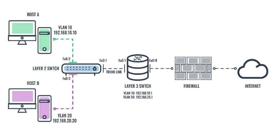
When the multilayer switch receives a packet in a VLAN intended at the Layer 2 switch, the multilayer switch performs routing. Let’s take a look at the diagram shown in Figure 3.0 below:

If Host A in VLAN 10, wants to send a message to Host B in VLAN 20, the steps it would take are as follows:
- Host A sends its unicast traffic to the directly connected L2 switch.
- L2 switch tags the unicast traffic as originating on VLAN 10 and forwards it to the L3 switch via the trunk link.
- The L3 switch removes the VLAN tag and forwards the unicast traffic internally to the VLAN 10 virtual interface.
- The L3 switch internally routes the unicast traffic to its VLAN 20 virtual interface and then retags the traffic, which it then forwards back to the L2 switch via the trunk link.
- L2 switch removes the VLAN tag of the unicast frame and forwards the frame directly to Host B on port fa0/3.
To configure multi-layer switch inter-VLAN routing on a Cisco device, in accordance with the diagram shown in Figure 3.0 above, use the IP addresses shown in Table 3.0 and follow the steps below:
Device | Interface | VLAN ID | IP Address | Subnet Mask | Default Gateway |
|---|---|---|---|---|---|
L3 Switch | Fa0/0 | N/A | 192.0.0.1 | 255.255.255.0 | 192.0.0.2 |
SVI 10 | VLAN 10 | 192.168.10.1 | 255.255.255.0 | N/A |
|
SVI 20 | VLAN 20 | 192.168.20.1 | 255.255.255.0 | N/A |
|
Host A | NIC | VLAN 10 | 192.168.10.10 | 255.255.255.0 | 192.168.10.1 |
Host B | NIC | VLAN 20 | 192.168.20.20 | 255.255.255.0 | 192.168.20.1 |
Table 3.0 IP address detail for Figure 3.0
Step 1: Create VLANs (VLANs 10 and 20) on the L2 switch
Description | Command |
|---|---|
Enter global configuration mode | L2-Switch# conf t |
Create VLAN 10 | L2-Switch(config)# vlan 10 |
Give a name to VLAN 10 | L2-Switch(config-vlan)# name Admin-dept |
Create VLAN 20 | L2-Switch(config-vlan)# vlan 20 |
Give a name to VLAN 20 | L2-Switch(config-vlan)# name Finance-dept |
Exit the VLAN config mode | L2-Switch(config-vlan)# exit |
Check if the VLANs were created | L2-Switch#show vlan brief |
Step 2: Assign the VLANs to the L2 switch ports
Description | Command |
|---|---|
Enter global configuration mode | L2-Switch# conf t |
Enter interface config. mode for fa0/2 | L2-Switch(config)# interface fa0/2 |
Set the port to access mode | L2-Switch(config-if)#switchport mode access |
Assign VLAN 10 to interface fa0/2 | L2-Switch(config-if)#switchport access vlan 10 |
Exit the interface | L2-Switch(config-if)# exit |
Enter interface configuration for fa0/3 | L2-Switch(config)# interface fa0/3 |
Set the port to access mode | L2-Switch(config-if)#switchport mode access |
Assign VLAN 20 to interface fa0/3 | L2-Switch(config-if)#switchport access vlan 20 |
Exit the interface | L2-Switch(config-if)# exit |
Enter interface configuration for fa0/1 | L2-Switch(config)# interface fa0/1 |
Set the encapsulation type to 802.1Q on the interface | L2-Switch(config-if)# switchport trunk encapsulation dot1q |
Set the port to trunk mode | L2-Switch(config-if)# switchport mode trunk |
Exit the interface | L2-Switch(config-if)# exit |
Save all configuration | L2-Switch# copy running-config startup-config |
Step 3: Enable L3 routing and create VLANs (VLANs 10 and 20) on the L3 switch
Description | Command |
|---|---|
Enter global configuration mode | L2-Switch#conf t |
Enable L3 routing | L3-Switch(config) # ip routing |
Create VLAN 10 | L3-Switch(config)#vlan 10 |
Give a name to VLAN 10 | L3-Switch(config-vlan)# name Admin-dept |
Create VLAN 20 | L3-Switch(config-vlan)# vlan 20 |
Give a name to VLAN 20 | L3-Switch(config-vlan)# name Finance-dept |
Exit the VLAN config mode | L3-Switch(config-vlan)# exit |
Enter interface configuration for fa0/1 | L3-Switch(config)# interface fa0/1 |
Set the encapsulation type to 802.1Q on the interface | L3-Switch(config-if)# switchport trunk encapsulation dot1q |
Set the port to trunk mode | L3-Switch(config-if)#switchport mode trunk |
Exit the interface | L3-Switch(config-if)# exit |
Save all configuration | L3-Switch)# copy running-config startup-config |
Step 4: Configure Switch VLAN Interfaces (SVI)
Description | Command |
|---|---|
Enter global configuration mode | L3-Switch# conf t |
Create a virtual interface for VLAN 10 and enter interface configuration mode. | L3-Switch(config)# interface vlan10 |
Configure a static route to reach VLAN 10 | L3-Switch(config-if)# ip address 192.168.10.1 255.255.255.0 |
Activate interface | L3-Switch(config-if)# no shut |
Exit the interface | L3-Switch(config-if)# exit |
Create a virtual interface for VLAN 20 and enter interface configuration mode | L3-Switch(config)# interface vlan20 |
Configure a static route to reach VLAN 20 | L3-Switch(config-if)# ip address 192.168.20.1 255.255.255.0 |
Activate interface | L3-Switch(config-if)# no shut |
Exit the interface | L3-Switch(config-if)# exit |
Step 5: Configure a routed port for connecting to the firewall on the L3 switch
Description | Command |
|---|---|
Enter global configuration mode | L3-Switch# conf t |
Enter interface configuration for fa0/0 | L3-Switch(config)# interface fa0/0 |
Interface description | L3-Switch(config-if)# description to Internet Firewall |
Creates an L3 port on the switch’s physical port | L3-Switch(config-if)# no switchport |
Configure IP address | L3-Switch(config-if)# ip address 192.0.0.1 255.255.255.252 |
Configure default route towards the firewall | L3-Switch(config)# ip route 0.0.0.0 0.0.0.0 192.0.0.2 |
Exit the interface | L3-Switch(config-if)# exit |
Save all configuration | L3-Switch)# copy running-config startup-config |
Again, a ping between Host A and Host B will be successful because the two VLANs are now interconnected through the multi-layer switch. Multilayer switch inter-VLAN routing is faster and more scalable than any other inter-VLAN routing implementation. This is because routers are limited by the number of available physical interfaces or ports, as well as the amounts of traffic that can be accommodated on the trunk link at one time. However, a multilayer switch does not totally replace the functionality of a router, as routers support a wide range of other supplementary features and capabilities. The table below is a comparison of the various inter-VLAN routing methods discussed.
Metric | Traditional Inter-VLAN Routing | Router-on-a-Stick | Multilayer Switch |
|---|---|---|---|
Supported routing protocol on switch | Static routing | Static routing | Static and dynamic routing |
Port Mode | Access mode | Trunk mode | Trunk mode |
Bandwidth | No bandwidth contention | Bandwidth contention | No bandwidth contention |
Latency | High | Medium | Low |
Scalability | Poor | Poor | Excellent |
Number of physical interfaces | One physical interface per VLAN | One physical interface for many VLANs | One physical interface for many VLANs |
TCO | High | Medium | Low |
Configuration Complexity | Low | Medium | High |
Acceptability | Archaic – No longer implemented | Modern–widely implemented | Modern–widely implemented |
Ideal for | Legacy networks | SME networks | Large enterprise networks |
Table 4.0 Comparison of the various inter-VLAN routing method
Inter-VLAN Routing Configuration FAQs
What is inter-VLAN routing?
You can forward traffic from one virtual LAN to another and this technique is called inter-VLAN routing.
What is the benefit of inter-VLAN routing?
VLANs can be used to enforce security, creating different zones of security levels for different users or applications. However, in many cases, it is still necessary for traffic to pass from one VLAN to another.
For example, imagine that you want to maintain two separate networks on your site because you need strong security for one and restricted access. However, imagine that you have one administrator for both networks and you put that admin account on the top security network. That administrator will still need access to the other network. By virtualizing the two networks onto the same infrastructure you cut costs and you can still have the same types of traffic throughput thanks to inter-VLAN routing.
What are the three methods for inter-VLAN routing?
There are three types of inter-VLAN routing and these are:
- Legacy Inter-VLAN routing Uses a router with several Ethernet sockets, linking each to a switch port in different VLANs. Traffic can then route from one VLAN to another through the router.
- Router-on-a-Stick Only one router Ethernet interface is needed and this is linked to a switch as a trunk connection. Each VLAN is defined through software as a subinterface with traffic tagged accordingly. Thus, all traffic for all VLANs is sorted in the router and can be retagged to move it from one VLAN to another.
- Switched Virtual Interfaces (SVIs) This technique runs on a Layer 3 switch. This is the most common method used today and it is very similar to the Router-on-a-Stick method. Each VLAN gets a virtual interface within the switch and so traffic can have tags swapped within the device to move from VLAN to another.


Thank you
Nice tutorial, thanks.
I have a two questions related to my situation at home which is as follows:
– 1 router with integrated WLAN access point
– the home router does not support VLANs and. VLAN routing as most home routers do not (Fritzbox in my case)
– majority of traffic is from and to the internet through the router
– switch with layer 3 functionallity is present (manages layer 2+ ( with some layer 3 functionallity like VLAN routing) to be specific, a d-link dgs-1210-20)
Questions:
– what happens if the router is connected to the switch with a cable for each VLAN (with the idea to increas tragfic capacity)?
To my understamding this shoild work if the connections bellong to separate portbased VLANs.
– How are theWLAN clients handled? Can they be assingnrd to different VLAN as well?
Very very helpful.👍🏿
Thank you 👏🏿👏🏿
Thanks
Thank you, very good tutorial
Thank u
Thank you for this nice article.
Very good lecture
yes